.Reading status (reading the status of the relay (on/off))
Channel 1 : 55 56 00 00 00 01 00 AC
Channel 2 :55 56 00 00 00 02 00 AD
Channel 3 :55 56 00 00 00 03 00 AE
Channel 4 :55 56 00 00 00 04 00 AF
Channel 5 :55 56 00 00 00 05 00 B0
Channel 6 :55 56 00 00 00 06 00 B1
Channel 7 :55 56 00 00 00 07 00 B2
Channel 8 :55 56 00 00 00 08 00 B3
2.Relay open (issue this command, Relay open, COM connect to NO)
Channel 1 : 55 56 00 00 00 01 01 AD
Channel 2 :55 56 00 00 00 02 01 AE
Channel 3 :55 56 00 00 00 03 01 AF
Channel 4 :55 56 00 00 00 04 01 B0
Channel 5 :55 56 00 00 00 05 01 B1
Channel 6 :55 56 00 00 00 06 01 B2
Channel 7 :55 56 00 00 00 07 01 B3
Channel 8 :55 56 00 00 00 08 01 B4
3.Relay close (issue this command, Relay close, COM disconnect NO and COM connect to NC)
Channel 1 : 55 56 00 00 00 01 02 AE
Channel 2 :55 56 00 00 00 02 02 AF
Channel 3 :55 56 00 00 00 03 02 B0
Channel 4 :55 56 00 00 00 04 02 B1
Channel 5 :55 56 00 00 00 05 02 B2
Channel 6 :55 56 00 00 00 06 02 B3
Channel 7 :55 56 00 00 00 07 02 B4
Channel 8 :55 56 00 00 00 08 02 B5
4.Relay toggle (Relay status reversal, if COM connect to NO, this command will Disconnect COM to NO and Reverse COM connect to NC, and vice versa)
Channel 1 : 55 56 00 00 00 01 03 AF
Channel 2 :55 56 00 00 00 02 03 B0
Channel 3 :55 56 00 00 00 03 03 B1
Channel 4 :55 56 00 00 00 04 03 B2
Channel 5 :55 56 00 00 00 05 03 B3
Channel 6 :55 56 00 00 00 06 03 B4
Channel 7 :55 56 00 00 00 07 03 B5
Channel 8 :55 56 00 00 00 08 03 B6
5. Relay momentary (Relay COM connect to NO, disconnect after 200MS)
Channel 1 : 55 56 00 00 00 01 04 B0
Channel 2 :55 56 00 00 00 02 04 B1
Channel 3 :55 56 00 00 00 03 04 B2
Channel 4 :55 56 00 00 00 04 04 B3
Channel 5 :55 56 00 00 00 05 04 B4
Channel 6 :55 56 00 00 00 06 04 B5
Channel 7 :55 56 00 00 00 07 04 B6
Channel 8 :55 56 00 00 00 08 04 B7
6. Relay Interlock
Channel 1 : 55 56 00 00 00 01 05 B1
Channel 2 :55 56 00 00 00 02 05 B2
Channel 3 :55 56 00 00 00 03 05 B3
Channel 4 :55 56 00 00 00 04 05 B4
Channel 5 :55 56 00 00 00 05 05 B5
Channel 6 :55 56 00 00 00 06 05 B6
Channel 7 :55 56 00 00 00 07 05 B7
Channel 8 :55 56 00 00 00 08 05 B8
RelayModule returncommand
Once issue a command, will have a return frame, 7th byte of return frame indicates the status of relay.
1.Return relay open(return this command, means COM connect to NO)
Channel 1 : 33 3C 00 00 00 01 01 71
Channel 2 :33 3C 00 00 00 02 01 72
Channel 3 :33 3C 00 00 00 03 01 73
Channel 4 :33 3C 00 00 00 04 01 74
Channel 5 :33 3C 00 00 00 05 01 75
Channel 6 :33 3C 00 00 00 06 01 76
Channel 7 :33 3C 00 00 00 07 01 77
Channel 8 :33 3C 00 00 00 08 01 78
2.Return relay close (return this command, means COM disconnect NO and COM connects to NC)
Channel 1 : 33 3C 00 00 00 01 02 72
Channel 2 :33 3C 00 00 00 02 02 73
Channel 3 :33 3C 00 00 00 03 02 74
Channel 4 :33 3C 00 00 00 04 02 75
Channel 5 :33 3C 00 00 00 05 02 76
Channel 6 :33 3C 00 00 00 06 02 77
Channel 7 :33 3C 00 00 00 07 02 78
Channel 8 :33 3C 00 00 00 08 02 79
Connecting Relay Module to WIZ750SR board
You need a DC12V to control the relay module. "LOAD"may be LED lights, fans, motors and other DC AC equipment
Wiring Relay Module
Wiring Relay Module
To connect external sensors to WIZ750SR module, I have soldered a right angle pins header to GPIO connectors.
Right angle pins Header
Right angle pins Header
Right angle pins header soldered to WIZ750SR module
Right angle pins header soldered to WIZ750SR module
Wiring sensors to GPIO Ports (VCC, GND Signal pin goes to a I/O port pin (A,B, C or D)
Wiring sensors to GPIO Ports (VCC, GND Signal pin goes to a I/O port pin (A,B, C or D)
WIZ750SR EVB + Relay Module + sensors
WIZ750SR EVB + Relay Module + sensors
Software for controlling relay module
The software was developed using.Net Framework and C# language. It's a single window application with a toolbar and 3 different zones.
Software Main Screen
Software Main Screen
The upper part is the toolbar : you can configure connection parameters (IP Address, TCP Port and connection password). Please note that the screenshots was taken with my private IP address because I don't want to share my public IP especially with a relay module connected behind my router :-)
Next to connection parameters. You have shortcuts for:
connecting to server
disconnecting from server
open all relays
close all relays
momentary open all relay (open, wait 200ms and close)
show configuration screen
Toolbar
Toolbar
In the left side, you have 8 pictures representing 8 relays. Each relay is represented by a state image (red background when it is closed and green background when it is open), a number representing the channel board in relay module and a user-friendly name that can be changed)
Relays States' zone
Relays States' zone
You can operate each relay with your mouse:
Left button click : momentary open the clicked relay
Right button click : interlock the relay, means that when let's say relay 5 is interlocked, you can not operate other relays unless you right-click again on relay 5.
Double click : reverse the relay state, if the relay is closed then send open command and if relay is open then send close command
Relays states are updated to be able to see in real time what are relays states.
on the right, you have triggers zone and sensors zones.
Triggers zone
Triggers zone
Trigger Zone is a very powerful feature to add custom trigger to your connected module. A trigger let you define a set of conditions (hardware & software defined) where when they are met, you can send specific commands to the relay module. We will see later how to configure triggers and some use cases.
Trigger zones consists of four sections (one section per trigger). In each section, you have the condition in blue, the output command in green, the last time the trigger has been activated in black and an icon indicating if the trigger is active or not. When the trigger is inactive, all the output command are deactivated.
The sensors zone below the triggers zone allows you to add external sensors to your connected module (up to four). A sensor can be either analog or digital. Each sensor is identified by an I/O port on the WIZ750SR EVB, a picture indicating if it is digital, analog or inactive and a user-friendly name. Sensors can be fully customized.
Sensors zone
Sensors zone
Tthe Software can be customised by editing the App.Config XML file (in the same directory than the executable file) manually or using Configuration Screen (shortcut from the toolbar)
Application configuration screen
Application configuration screen
An example of a config file is presented below:
<?xml version="1.0" encoding="utf-8" ?>
<configuration>
<startup>
<supportedRuntime version="v4.0" sku=".NETFramework,Version=v4.6.1" />
</startup>
<appSettings>
<!--Connection Parameters!-->
<add key="Password" value="aaaaaaaa"/>
<add key="IPAddress" value="192.168.0.17"/>
<add key="Port" value="5000"/>
<!--Channels Labels'-->
<add key="Channel1" value="Feeder"/>
<add key="Channel2" value="Light-Liv"/>
<add key="Channel3" value="Light-Kit"/>
<add key="Channel4" value="Fan"/>
<add key="Channel5" value="Router"/>
<add key="Channel6" value="Room n°6"/>
<add key="Channel7" value="Room n°7"/>
<add key="Channel8" value="Room n°8"/>
<!--A Port Definition-->
<add key="PortAName" value="Door-Open"/>
<add key="PortAType" value="digital"/>
<!--B Port Definition-->
<add key="PortBName" value=""/>
<add key="PortBType" value="analog"/>
<!--C Port Definition-->
<add key="PortCName" value="Moisture"/>
<add key="PortCType" value="analog"/>
<add key="PortCMinValue" value="0"/>
<add key="PortCMaxValue" value="2300"/>
<!--D Port Definition-->
<add key="PortDName" value="Temperature"/>
<add key="PortDType" value="analog"/>
<add key="PortDFunction" value="CalcTemp"/>
<!--Trigger 1 Definition'-->
<add key="Condition1" value="Not Channel1"/>
<add key="Output1" value="Open Channel7|Close Channel1"/>
<add key="isTrigger1Active" value="false"/>
<!--Trigger 2 Definition'-->
<add key="Condition2" value="(Temperature+5) above 32 and Moisture below 25"/>
<add key="Output2" value="Open Channel7|Open Channel3"/>
<add key="isTrigger2Active" value="true"/>
<!--Trigger 3 Definition'-->
<add key="Condition3" value="every 120 minutes"/>
<add key="Output3" value="Momentary Channel8"/>
<add key="isTrigger3Active" value="true"/>
<!--Trigger 4 Definition'-->
<add key="Condition4" value="at 18:18"/>
<add key="Output4" value="Toggle Channel8"/>
<add key="isTrigger4Active" value="false"/>
</appSettings>
</configuration>
Connection Parameters : this section lets you define parameters to connect to TCP server ( IP Address, TCP Password and TCP Port)
Channels labels' : in this section, you can give a user-friendly name to each relay channel (e.g. Fan, Motor, light…)
I/O ports definition : in this section, you can configure external sensors by setting communication mode for the 4 GPIO ports of SR750SR (Port A, B, C and D). If you want the port to be active, you have to define the PortName parameter, if left blank the port will be inactive. The PortType can be analog input or digital input. For a digital port, no further parameter is required, the output value will be either 0 or 1. For analog ports, you have to tell the software how to deal with raw output value read by sensor. For this, you have three ways :
Pass-Through mode: in this mode, the raw value sent by a sensor is simply used and displayed in the screen without any modification
Percentage mode: in this mode, you have to provide minValue and maxValue parameters. The resulting value will be calculated as follows : displayed value (%) = 100 *(read value - minValue) / maxValue
Custom function mode: in this mode, you have to provide the name of a user defined C# public function. This function will be called every time we need to read value from the sensor. The read value will be passed as an argument to the function (in string format).
To define the type of the port, you can use WIZnet S2E configuration tool and choose between Analog input and Digital input. Also, you can determine min and max Value for an analog sensor by reading displayed value for different configurations (e.g. for a moisture sensor, you read the value in a dry environment (min Value) and in a complete wet environment (glass of water) for max value.
Configuring GPIO ports
Configuring GPIO ports
Triggers definition: you can define up to four triggers. To be active, a trigger must have the corresponding isTrigger[1..4]Active parameter set to true. You have three ways for defining a condition associated to a trigger:
1- on a periodic basis: with the following syntax (every x minutes) where x is a integer number >=1
2- at a specified time: with the syntax : at hh:mm where hh:mm is the desired time for activating the trigger in 24hours time format
3- with a boolean expression: a boolean expression is a mix of :
operators : AND, IN, NOT, OR, ABOVE, BELOW, +, -, *, /, %
Channel Names : Channel[1..8] : this expression will evaluate to true when the relay is open and false otherwise
PortName : this will be replaced by final value obtained from the corresponding port
When trigger condition evaluates to true, the trigger output is executed. A trigger output is a set of commands separated by | symbol. A command is a combination of an order (Open, Close, Momentary, Toggle or Interlock) and a channel (Channel[1..8])
Main Window displaying live relays states and sensors values'
Main Window displaying live relays states and sensors values'
Trigger use case
Here, some real life usages of this project:
Simulate a presence : Turn light on every day at 20:05 and turn off at 23:45-> connect a floor lamp to channel 1, add a trigger 1 (condition ="at 20:05", output="Open channel1") and a trigger 2(condition="at 23:45", output="Close channel1")
Commanding an electronic fish feeder ( feed a fish every 12 hours) : connect fish feeder to channel 2, add a trigger 1 (condition="every 720 minutes", output="Momentary Channel2")
Automatic irrigation : Wire a moisture sensor on port A, plug an irrigation system to channel3 and add a trigger 1 (condition="MOISTURE below 20", output="Open Channel3"). Every time, the moisture is below 20%, irrigation system will be activated till the moisture level become above 20%)
Some words on source code
The source code compiles with Visual Studio .Net. VS2015 should also work. No extra libraries are required. The main file in source code is Mainform.cs .
What's Next
Here, is a list of improvements to this project:
Printing a 3d Enclosure
Adding a WIFI to Ethernet Bridge
Interfacing with an Arduino board to have access to more advanced sensors (I2C, SPI) and to make the system fully stand-alone ( settings may be stored on a SD card)
Porting Software to Linux (using Mono.Net)
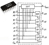
Schematics
Project Schematics
Montage wiz750sr vildryvptx
Code
Remote Relay Source codeC#
Compile with Visual Studio 2017
Credits
Amine Amri
Amine Amri
1 project • 0 followers
Follow Contact
Comments
Please log in or sign up to comment.
Please confirm your email before commenting. Haven't received a confirmation email? Resend. Contact us at
help@hackster.io for help.
1
2